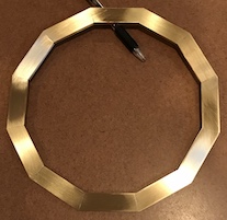
A dodecagon was planned for the frame instead of a circle to save money. A length of 3/16" X 3/4" brass flat was purchased. The first jig constructed was made of oak in the hope that keeping it wet would allow soldering the parts while sitting on the jig. The jig might also be useful for later marking the various divisions around the circumference of the dodecagon.
A square of 3/4" oak made from glued up 3 1/2" boards was cut to a 9 3/4" circle after drilling the center for a 1/4" hole. The circle cutting was done on the table saw with a 1/4" shaft fixed at 4 7/8" from the edge of the crosscut sled. A recess needed to be routed in the wooden circle to hold the 12 identical brass parts. The I.D. of this recess needs to be twice the inner radius of the inside of the dodecagon and the O.D. of the recess needs to be twice the outer radius of the outside dodecagon.
Dodecagons have both an inner circle that is tangent to the sides of the dodecagon and an outer circle that intersects the corners of the dodecagon. The radius of the inscribed circle is called the inner radius (r) and the radius of the circumscribed circle is called the circumradius (R). The two radii and the length of the sides (s) are all defined by the following relationships or equations.
| Feature | Label | Radii Formulas | Inverted Formulas |
|---|---|---|---|
| side length | s | ||
| inner radius | r | ||
| circumradius | R |
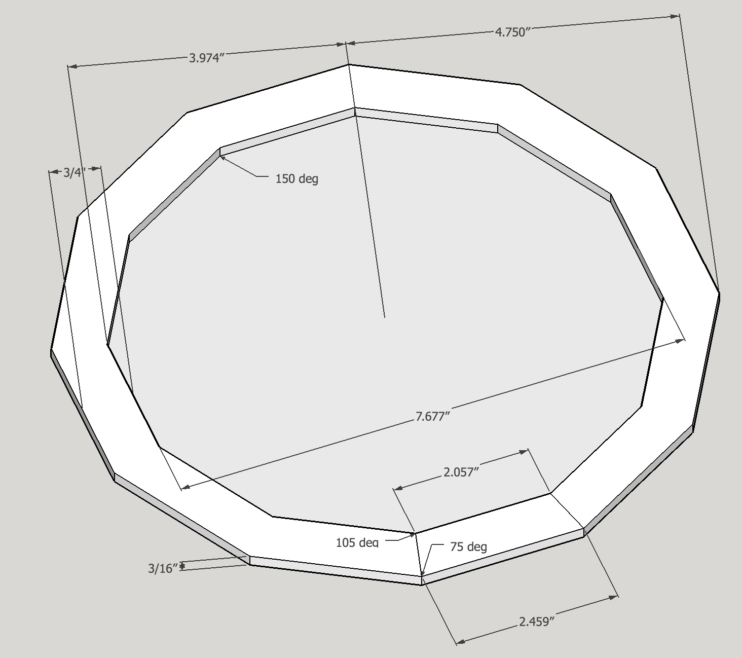
Given s, r, or R we can find the other parameters that define our dodecagon. There are actually two dodecagons; the first is the inside dodecagon of the frame and the second is the outer dodecagon, separated by the width of the brass used. For this wooden jig we need the inner radius for the smaller or inside dodecagon, rS, and the circumradius for the large dodecagon, RL. We also know that rS + 0.75" = rL, because the width of the brass used is 0.75". An approximate 9" O.D. for the frame was desired, because the Mars ring is planned to be a little over 7" O.D. An outside frame diameter of 9.5" was chosen. This defines RL = 4.75". From the equation in the table above sL, the longest side of the trapezoidal segment is 2.459".All of the formulas were incorporated in a spreadsheet and the following table shows the output based on a 0.75" part width and RL = 4.75".
| Parameter | Label | Size (in) |
|---|---|---|
| Large Dodecagon Circumradius | RL | 4.75 |
| Large Dodecagon Inner Radius | rL | 4.588 |
| Small Dodecagon Circumradius | RS | 3.974 |
| Small Dodecagon Inner Radius | rS | 3.838 |
| Long Side | sL | 2.459 |
| Short Side | sS | 2.057 |
The angles of the trapezoidal pieces are 90° ± half of the angle subtended by a side (360°/12 = 30°) or 90 + 15 = 105° and 90 - 15 = 75°. So returning to the wooden jig construction, a 1/8" deep recess with an I.D. = 7.676" (2rS) and an O.D. = 9.500" (2RL) needs to be made.
A router with a homemade circle cutting jig was used to cut the recess. The router bit was set 1/8" deep and the jig inner pin to bit distance was set to rS - 1/2 X pinO.D.. The pin used in this jig is 0.150" in diameter, so this distance is 3.763" as measured by inner calipers. Since the hole in the center of the wooden jig is 1/4" a pin to hold the pin was made from a 3/4" length of 1/4" round stock. It was drilled 1/2" deep with a #24 drill (0.152") and served as a good reducer for holding the router circle cutting jig pin. The small circle was routed. The distance from pin to bit was changed to RL + 1/2 X pinO.D as measured by outside calipers. The second circle was cut and the area between the two recesses was removed by reducing this pin-bit distance as needed. A 3/8" bit was used.
The twelve 2.5" pieces were cut with a hacksaw from a 3/16" X 3/4" X 36" brass bar. They ranged in size from 2.52 - 2.55". The ends were filed a bit on the corners to ensure the pieces would stack well. Six of the pieces were clamped together face-to-face with a C-clamp. The stack was placed in the mill vise. The angle plate was clamped to the mill table and the angle set to 15°. Since tan15° = 0.268, the rise for a 1" run is 0.268". A DTI was held in the spindle and set to read 0.005" while touching the angle plate. The spindle was raised 0.268" and the table was moved 1.000". The angle plate was adjusted (~0.020") until the DTI read 0.005". The measurement was checked by raising the spindle a further 0.268" and moving the table 1.000". The DTI then read 0.005". Some roughness was seen on the table surface, so this is probably only within 0.010". The mill vise was clamped to the angle plate.
The parts were clamped in the vise and squared to the vise so they were vertically square and resting on a parallel. The C-clamp was then applied and all things were tightened down. A fly cutter was used to produce the angle on the ends of the six stacked parts (~ 0.0075" per pass). The cuts sounded like a loud single cylinder engine. The feed was slow. After cutting one end of the stack it was flipped over to cut the other end making sure the stack was oriented correctly to give the trapezoids needed. After completing the second side the stack was checked for length (~ 0.040" too long) and replaced in the vise. Cutting continued until the length was 2.469" or 1-2 thou less than noted above to allow some room for the solder joint. The second stack of six parts was prepared similarly. When all were placed tightly in the wooden jig a gap of about 50 thou remained. This provides about 4 thou per solder joint, which should lead to a good solder joint as 0.002-0.004" is recommended.
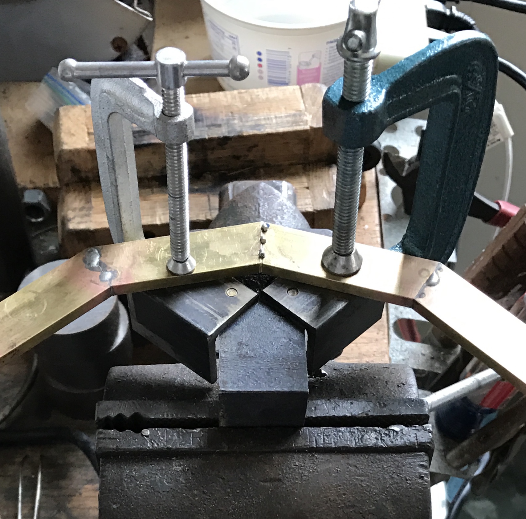
Wetting the oak jig did not prevent burning so that approach to soldering was abandoned. The oak jig was valuable though as a means of checking the accuracy of the angled milling. A simple jig was designed with two pieces of angle iron attached to a third piece of angle iron. The two were hald at angles relative to one another to provide a gap beneath the soldered joint. The third angle iron was held in a vise. The pieces were lightly clamped to the jig in the vise with C-clamps and adjusted so that a 0.004" shim fit tightly between them. The brass parts were fluxed and three small pieces of solder were laid on the joint gap. The brass was heated with a propane torch on both sides of the joint until the solder melted and flowed into the joint. Six pairs were made and these were then soldered together. The final join was surprisingly close. The entire process was then repeated for the second dodecagon. The final join in this case did not work so well. The ends needed to be sanded to fit and the resulting dodecagon was not completely flat. It seemed close enough, so work proceeded with it. Both dodecagons were sanded to about 400 grit to remove the traces of soldering and ready the brass for eventual polishing.
It was not until the bottom support and the top support were made and installed that this lack of flatness raised its ugly head. In order to screw the two dodecagons to the columns the frame had to be forced into place. This placed a lot of tension on the shafts holding the gear stacks. Consequently it was difficult to get the gears to move freely. At a minimum the warped dodecagon needs to be remade.
Back to the drawing board. After posting a query on the Hobby-Machinist forum about this project and getting a number of insightful replies the following course has been chosen. A 1/4" X 10" X 10" steel base will be used to mount a disk that has a 3.838" radius also made of steel and 1/4" thick. The mounting holes will match the mounting holes on the SB faceplate. A series of 12 holes will be drilled and tapped in the base a small distance outside the disk to hold clamps, one for each brass trapezoid. The base may be slotted where the joints will be soldered to minimize the chances of the part sticking to the base. This jig should allow complete dry assembly of the dodecagon, setting a .002 - .004" gap at each joint, and guaranteeing flatness. Unfortunately, the steel for the jig will cost about $50. That will be an incentive to make more orreries.
With the recently purchased metal in hand the aluminum and steel plates were lightly filed along the edges to get rid of sharp burrs. The faceplate was roughly centered on the aluminum plate and its four holes were transferred to the aluminum plate with a transfer punch. The plate was then drilled at the punch marks from 1/16" to 3/8". The four bolts (1", 3/8-16) fit nicely into the adjoining faceplate. The holes in the aluminum plate were then transferred to the steel plate and drilled up to 5/16". The holes were then tapped 3/8-16. These holes did not align quite as well as the faceplate, so the holes in the aluminum plate were opened an additional 1/64". This gave a good fit to the steel plate.
The aluminum plate center was marked and arcs were scribed in the corners with the calipers set at 3.838". The hacksaw was then used to cut off the corners of the plate. The octagonal aluminum plate affixed to the faceplate was placed on the SB lathe and the octagon was reduced to a circle.
It was realized at this point that the center scribed on the plate was not the same center as found on the lathe!! Clearly should have placed the plate on the faceplate and used the lathe to mark the center prior to cutting off the corners and reducing the octagon to a circle. Luckily, the diameter at this point was 7.91".
Once a circle had been formed the challenge was how to measure the 7+ inch diameter with a 6" caliper. This was attempted with the use of two 6" calipers. One was set at the desired radius (3.838") and locked. It was set to span from the edge to the middle of the disk. The second caliper was then used to measure from the inside of the first caliper to the other edge of the plate. The first measurement was 7.908" and the second was 7.912". This needs to be done more rigorously to get the desired precision. Possibly clamping the first locked caliper in place and then finding the greatest caliper to edge distance of the plate might be a more reproducible and accurate method. After taking off an additional 0.020 - 0.030", I still struggled to get a repeatable measurement. Finally went with a 12" ruler and measured the diameter at 7.672" (7 43/64") vs desired 7.676". This is within 0.010". Measured with the height gauge at 7.683" keeping it vertical with two 1-2-3 blocks. Returned to the lathe and took off a few thou and now via a couple of measurements it is within 5 thou. Decided this is good enough.
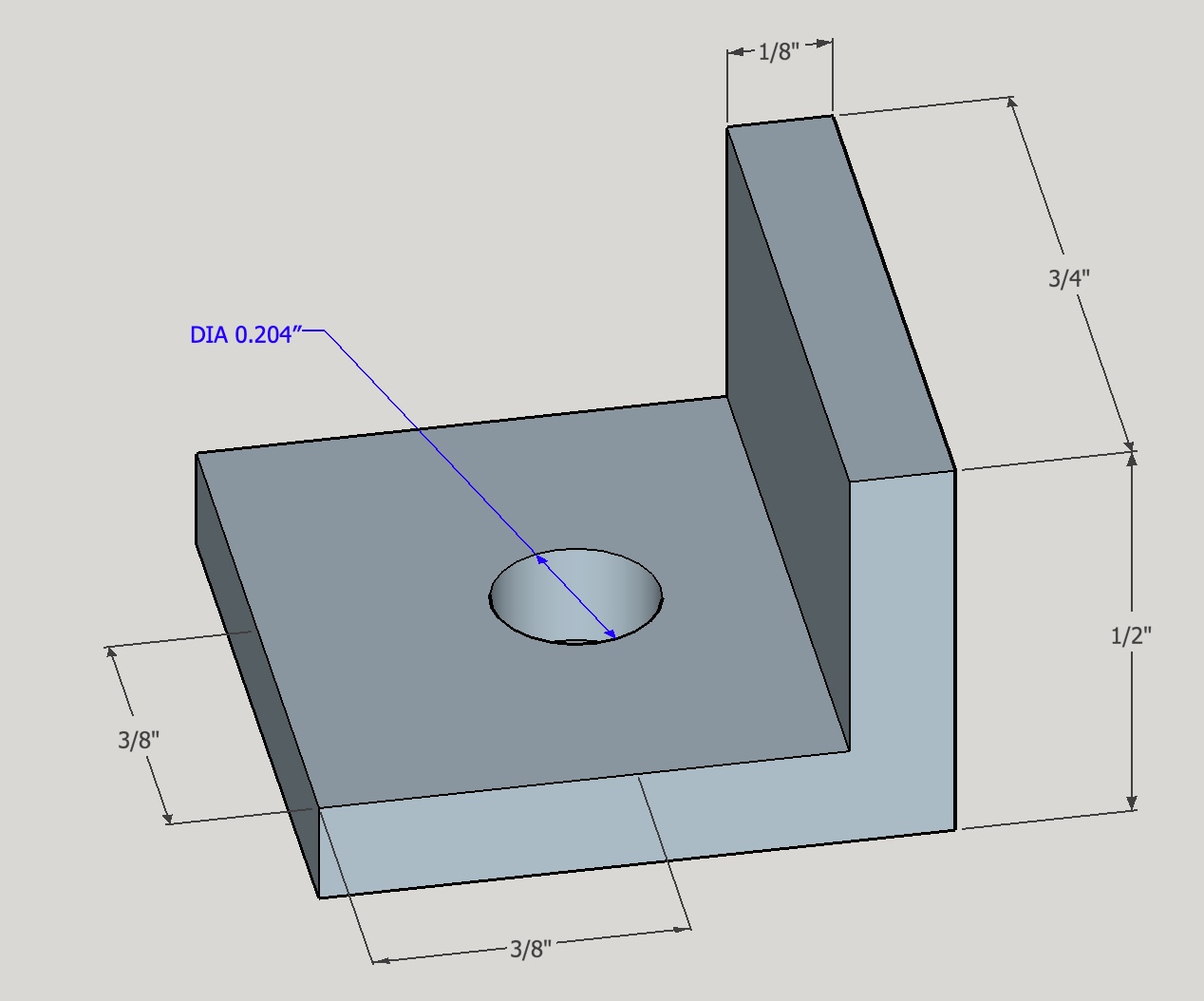
Started the clamps with a 12" length of 1/8" X 3/4" X 3/4" angle iron. A hole was drilled 3/8" from the end and then every 3/4", all 3/8" from the edge. The holes were drilled to 0.204" diameter as that is the size of the hole in the similar Sherline clamps. The holes were chamferred on both sides. The 12 clamps were all cut off with a hacksaw with each cut centered between holes. About 1/4" of the non-drilled side was then cut off as well. All edges and corners were lightly filed.
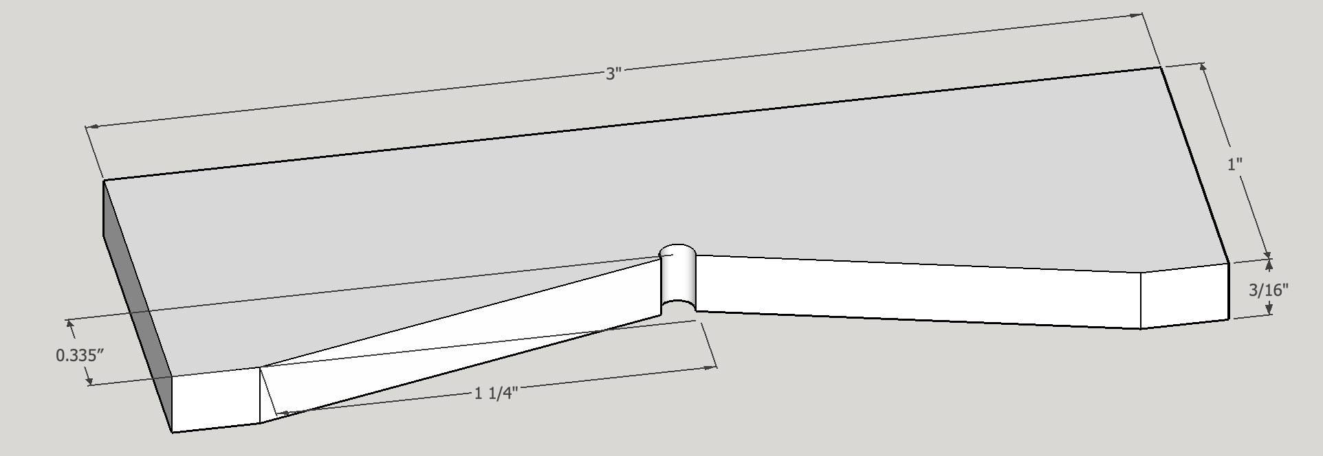
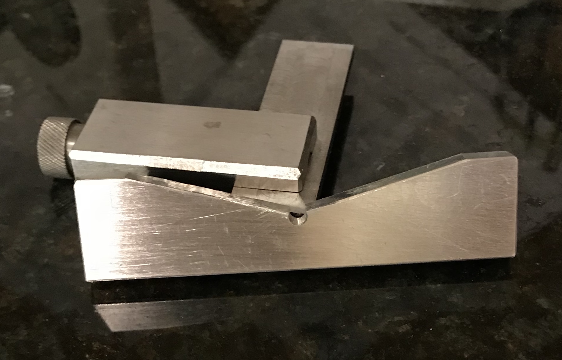
Setting the angles on the jig requires some precision so an angle jig was constructed as seen in the above plan. Most of the dimensions are unimportant; only the angle requires precision. A 3" length of 1/4" X 3/4" aluminum was cut from scrap. The ends were squared up in the vise on the mill as well as one long edge. A center line was scribed at 1.5" on one 3/4" side. The height gauge was set to 2.335" and used to scribe a mark on the part while it sat 2" high on two 1-2-3 blocks. This mark was lined up in the vise on the mill with the use of the edge finder's pointed end. It was center drilled and drilled with a #31 drill (0.120") as it was ready to hand.
The angle plate was set to 15° attached to the mill table and the vise attached to it. The aluminum was placed in the vise on a parallel. A dial test indicator (the one with the straight shaft) was used to fine tune the angle to precisely 15°. Since the angle plate was adjusted until a rise of 0.0268" for a table movement of 0.100" was found. All parts of the setup were tightened and the part was cut with a 5/16" end mill across the 1/4" dimension starting in the middle. Multiple passes were made as the cut got deeper. When about 1/4" on the end was left the part was turned in the vise and the other side of the angle was cut. The milling on this side was terminated when the two uncut ends were equal in length, 11/32".
The angle plate needed to be shortened by taking 5/8" off of each end to fit between the clamps.
Next came drilling the 12 holes in the steel plate around the aluminum plate. Taking one of the new clamps for a trial run on the tee slot in the Sherline lathe table gave 0.91" from the far side of the 3/4" wide brass plate to the center of the clamp screw. Consequently, the hole circle radius needs to be 3.838" + 0.91" = 4.75". This leaves about 1/16" between the outside of the brass plate and the edge of the screw. To transfer this distance to the steel plate requires transferring the center of the aluminum disk to the steel plate. Since there is no hole in the center of the disk, an alternative was sought. First, the orientation of the disk and steel plate was marked by aligned 'pips' made in both parts. A bar compass was set to the desired hole circle radius and used to mark the hole circle. The distance between the holes is determined by the following equation: where D is the bolt hole circle diameter, P is the angle between the holes or 360° divided by the number of holes, and R is the distance between holes. (See MW Vol. 19, No. 4, Aug/Sep 2006)
So in our case of 12 holes on a 4.75" bolt hole circle, the distance between holes is 9.5 X sin(15°) = 2.459". I set the compass to 2.459" and 'walked them' around a ring that had been scribed at the 4.75" diameter. These hole locations were punched and then drilled with a #21 drill and tapped 10-32.
An adapter was made so the dial test indicator could be used in the mill spindle. This was essentially a block of aluminum with a hole drilled in one side to accept the 10-32 screw that would hold the indicator to the block. At 90° to this hole the a 3/8" through hole was drilled and reamed. The ends of a 2" length of drill rod were faced and chamfered. This was inserted into the 3/8" hole for a very tight fit. It was necessary to sand the rod to get a sliding fit in the milling collet.
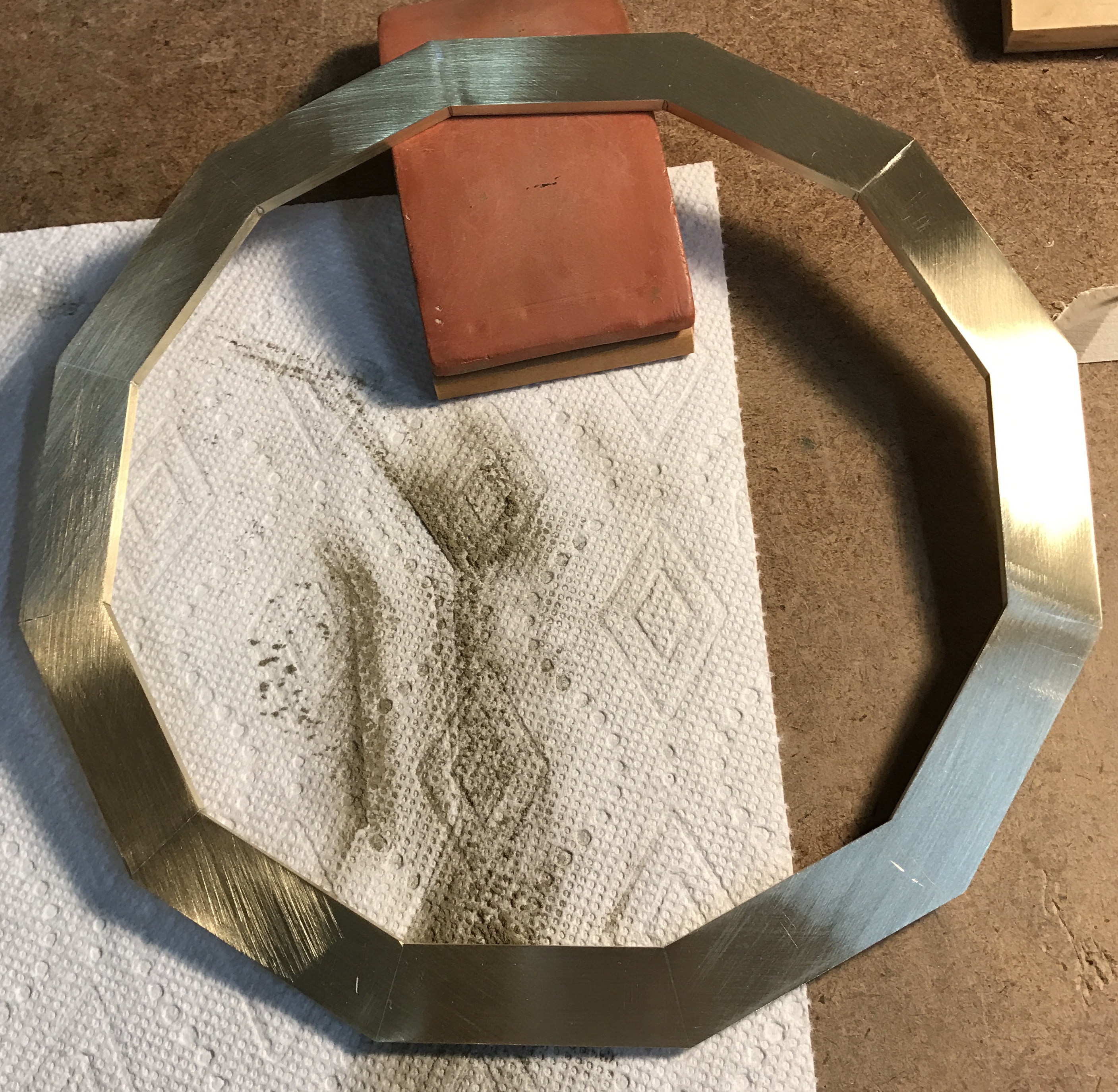
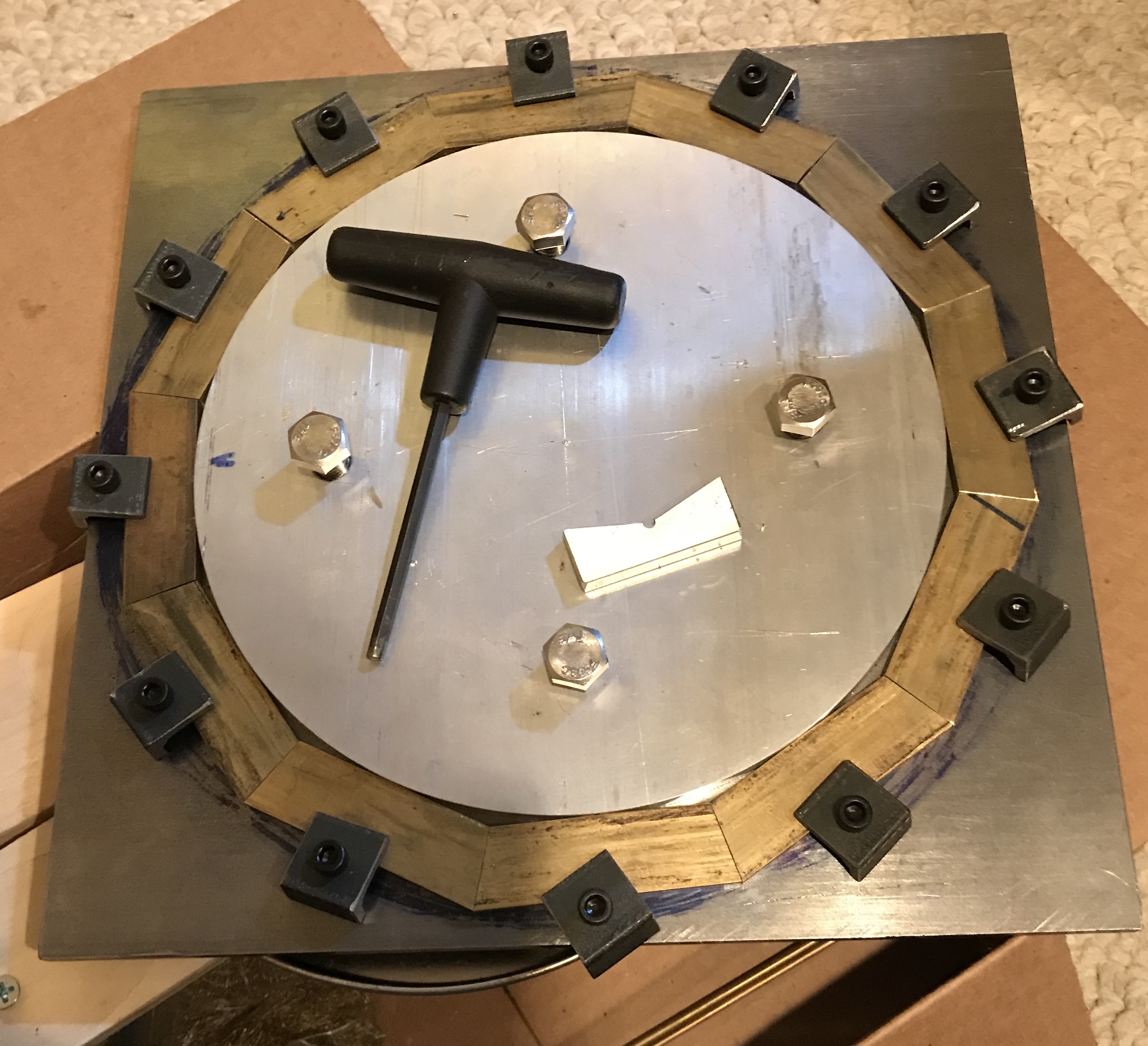
Twelve new dodecagon sides were cut at a 15° angle with a hacksaw at 2 9/16" on the long side. These were set in the vise and clamped as above and cut to length and to 15.00° on the mill as before. The angle table was carefully set to 15° with the dial test indicator and the vise was set parallel to the x-axis with the dial indicator. The twelve new sides were then clamped in the jig. They have not been set precisely in the following picture, though they are pretty close.
Spent some time to better align the pieces. Spark plug gapping feelers were used to get the gaps between the parts to be in the 2 - 4 thou range and to get a parallel gap. This required multiple trips around the dodecagon. When all parts were set the clamps were tightened. A joint was fluxed and then three 1/16" pieces of solder were placed on the joint, which was then heated with a propane torch until the soldered flowed into the joint. After completing all twelve joints the clamps were released and the frame was gently pried from the jig with a screwdriver.
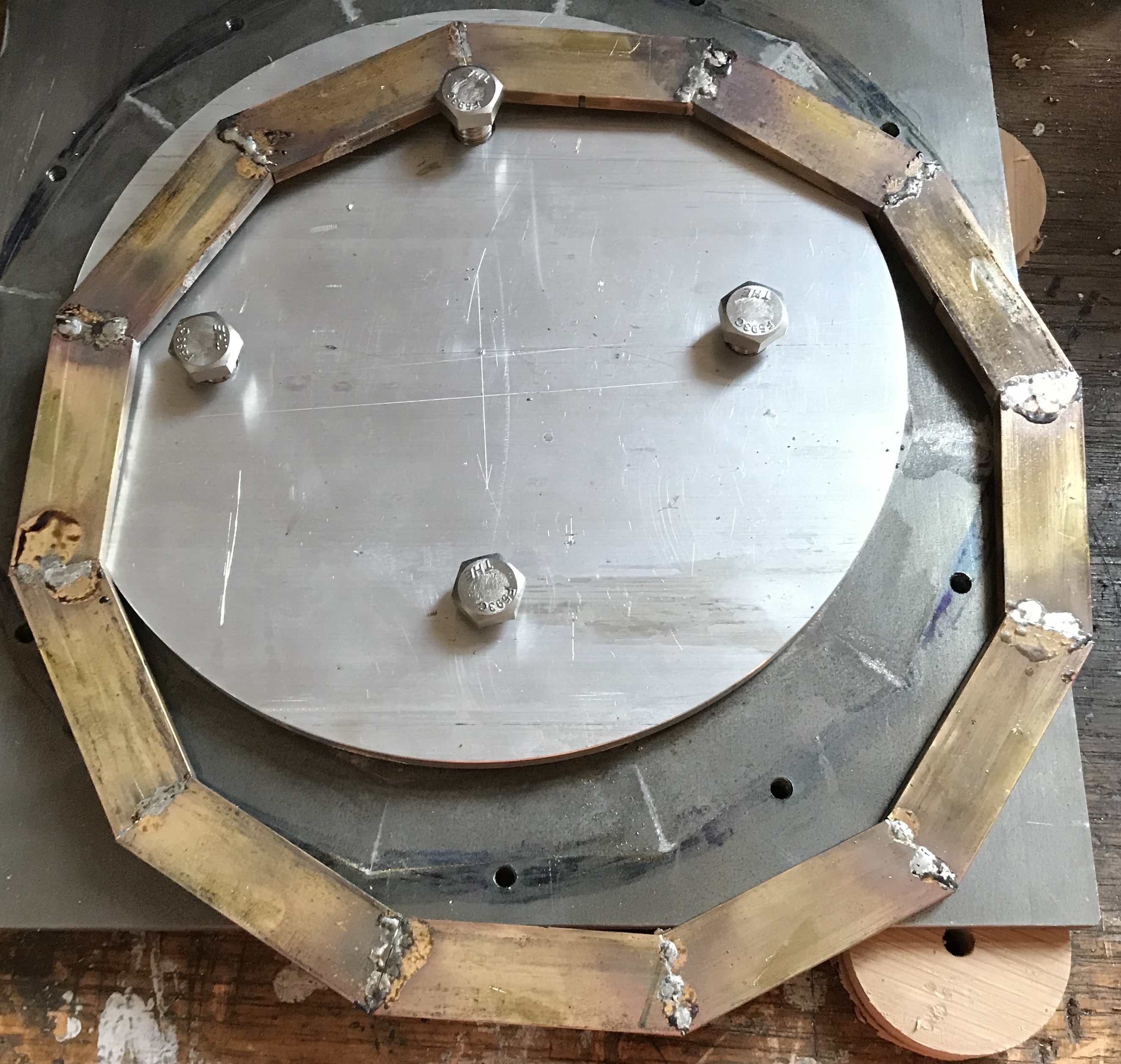
The frame was washed with soap and water to remove the acid and flux. Also to warm it up as the garage temperature was below freezing. The frame was then sanded by hand with successively 100, 150, 220, 320, and 400 grit paper. This left a nice finish that is ready for polishing when a polishing wheel is purchased.
See Orrery Odds & Ends & Assembly for more details on the techniques mentioned below. The new ring was aligned with the old ring by eye and the two were clamped in two places. The holes were transfered with a 3/16" transfer punch after setting the two rings with clamps across a large block of wood. This placed the supporting block directly under two holes at a time. The rings were marked for alignment and the new ring's top was also marked. The hole locations were checked for alignment with the tops of the columns as well. The rings were separated and the columns were installed in the bottom ring. The pointed screws were placed in the column tops and the top ring, appropriately aligned, was placed on the points. The points all aligned well, so no hole position adjustments were required. With the ring clamped in a vise on parallels in the mill the holes were started with a center drill and drilled through with a #10 drill. The holes were deburred. Alignment was perfect with the columns installed in the lower ring.